


 15 / 20

WINTER 2015 | MARINE TECHNICIANTODAY
15
the motor ages. Unlike a 4-stroke which increases its emissions output
as the pistons, rings, and valves start to deteriorate, an EMM 2-stroke
often becomes even “cleaner” over time due to the pulse counting
combined with the injector re-calibrations, according to Evinrude
project engineer George Broughton.
Engine temperature, RPM, throttle opening, charging voltage and
barometric pressure are just a few of items monitored by the engine
management module. After gathering the sensor information, an EMM
controls the output and the timing of the fuel system and the ignition
system to make sure that each cylinder delivers optimum power at that
particular moment. This is equivalent to getting a tune up every time a
cylinder gets ready to fire. At 5800 rpm this happens around 576 times
per second on a 6 cylinder outboard. According to Broughton, “The EMM
handles about eight million calculations per minute.”
The EMM cannot think, it only gathers information, compares it to its
look-up table (MAP), then sends specific commands to operate the
individual fuel injectors and the ignition system. In addition, it manages
the battery charging along with the engine’s oiling system. The EMM
also generates a tachometer pulses, the NMEA2000 networking data,
and signals warning alarms if required. A unique feature of the Evinrude
E-TEC EMM is the ability of four built-in LEDs to serve as a visual engine
diagnostic system. The yellow sticker on the cover informs the operator
how to troubleshoot the engine using the illumination sequence of
the LEDs. There are three different diagnostic modes that utilize the
LEDs – key on - engine off, engine cranking and engine running. In
each of these modes the illuminated LEDs point to a specific system
experiencing an abnormality.
To better understand how an EMM operates, visualize an executive
sitting behind a desk. His various employees, the input sensors, record
data then in turn barge into his office and start telling him:
“Hey boss, the motor is running 4000 rpm”
“Hey boss, the engine temperature is 160°”
“Hey boss, the throttle is 75% open”
“Hey boss, the air temp is 82°”
“Hey boss, the battery is at 14 volts”
“Hey boss, the barometric pressure is 29.92”
The boss-man gathers all the information then refers to his look-up table
(MAP) that says if the throttle is 3/4 and the rpm is 4000, then the spark
timing should be at this particular setting and that fuel delivery should
be this specific amount. Other data such as air and engine temperature,
exhaust backpressure, and barometric pressure are factored in to slightly
modify (trim) the spark timing and the fuel flow commands if needed.
After reviewing the information and consulting the MAP, the decision
maker shouts commands to other workers, the output actuators:
“Hey You, Set the #1 spark timing to 28° before top dead center”
“Hey You, Set the #1 fuel injector to deliver X amount of gasoline 1
microsecond before the sparkplug fires”
“Hey You, Increase the battery voltage to 14.5 volts”
“Hey You, Pulse the oil injector 2 times”
“Hey You, Tell the tachometer to read 4000 rpm”
This sequence of gathering engine data and the EMM commanding the
various actuators results in complete combustion inside each cylinder
for best power and fewest emissions. On a V-6 outboard over 133,000
computer calculations occur every second at wide open throttle. The
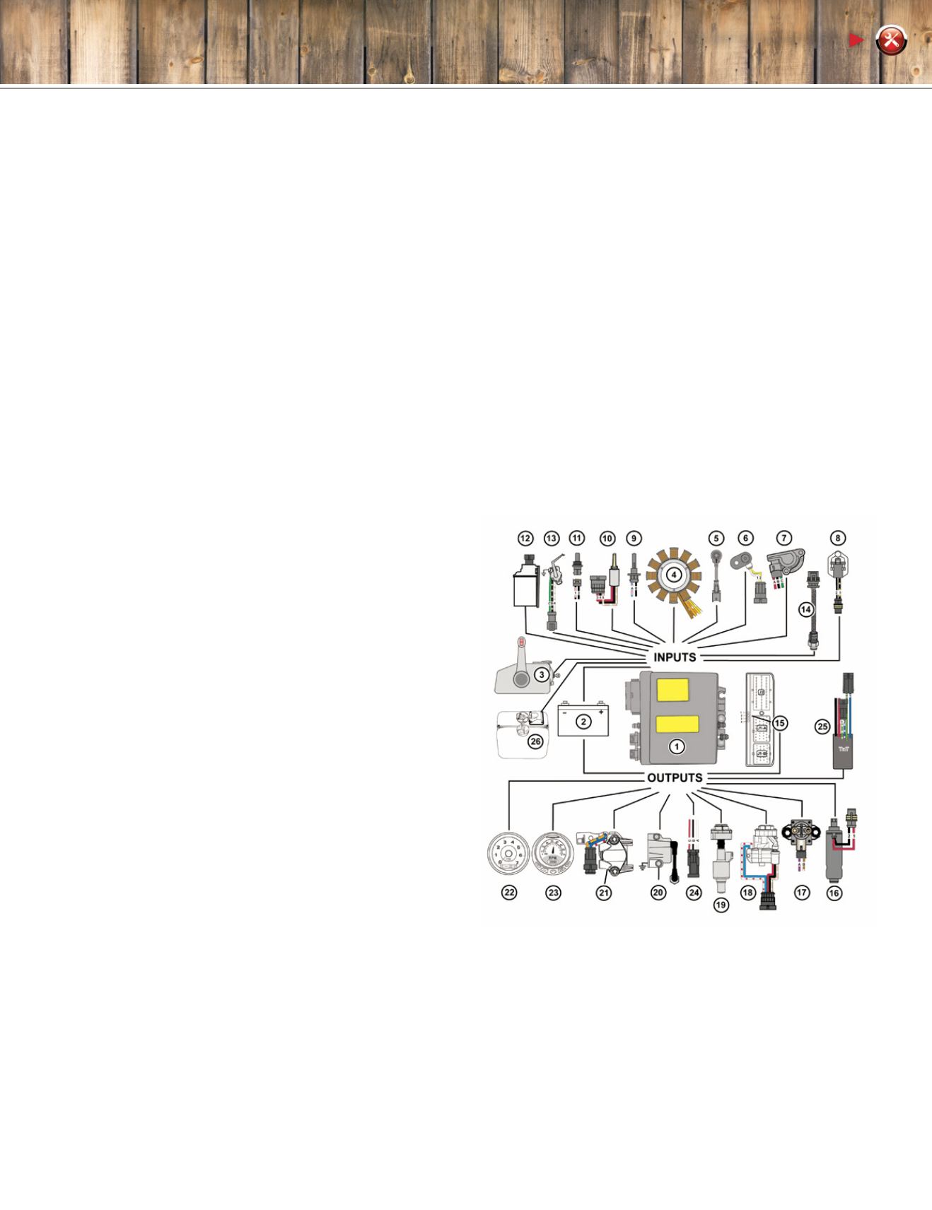
image below illustrates the various input sensors and output actuators
found on a V-6 EMM.
TODAY’S TECHNICIAN
1. Engine Management Module (EMM)
2. Battery (12 volt)
3. Key switch (switched B
+
, start signal)
4. Stator
5. Knock sensor
6. Crankshaft Position Sensor (CPS)
7. Throttle Position Sensor (TPS)
8. Shift Interrupt Switch
9. Air Temperature Sensor (AT)
10. Oil Pressure Sensor (component of 18)
11. Engine Temperature Sensor(s)
12. Water in Fuel Sensor / Fuel Filter
13. Trim / Tilt Sending Unit
14. Water Pressure Sensor w/adaptor harness
15. LED indicators
16. Fuel Pump (high pressure)
17. Starter Solenoid
18. Oil Injection Pump and Manifold
19. Rear Oil Injector and Manifold
20. Ignition Coil
21. Fuel Injector
22. Tachometer/
SystemCheck
Gauge
23.
NMEA2000
Network Digital Data
24. Diagnostic Connector
25. Trim and Tilt Relay Module
26. Oil Level Switch
LEGEND